Chapter 8 · Capturing Sound: Microphones, Acoustics & Gear
Cables and Patchbays
“A chain is only as strong as its weakest link.”
—Proverb
By the end of this chapter, you will be able to:
- Explain how common-mode rejection allows balanced cables to maintain signal integrity over long runs and why unbalanced cables are limited to approximately 25–30 feet before noise becomes problematic
- Identify the six analog connector types—XLR, TRS, TS, TT, RCA, and DB25—and select the correct connector for a given studio application
- Compare the five professional digital audio formats—AES/EBU, S/PDIF, ADAT Lightpipe, MADI, and Dante/AES67—by channel capacity, cable type, and appropriate use case
- Distinguish among the four computer and interface connection types—USB, Thunderbolt, DigiLink, and BNC word clock—and describe the role each plays in a studio signal chain
- Demonstrate the strip-tin-solder sequence for constructing a balanced audio cable and verify continuity of every conductor using a cable tester
- Configure a patchbay in open, normalled, half-normalled, and parallel modes, and explain how half-normalled routing enables signal taps and hardware inserts without breaking the default signal path
- Select between a simple headphone distribution amplifier and a personal cue-mix system—such as Aviom or Hear Technologies—based on the monitoring needs of a tracking session
- Diagnose a ground loop using the star-grounding approach and apply the appropriate remedy—power conditioning, DI ground lift, or isolation transformer—as well as identify and mitigate common RF and EMI interference sources
Nobody gets into audio engineering because they are passionate about cables. But I have watched sessions in my own studio grind to a halt over a single bad XLR connection—hours of troubleshooting, a frustrated artist sitting idle, and the culprit turned out to be a cold solder joint on a cable that looked perfectly fine from the outside. I was on my hands and knees behind the rack, cable tester in hand, swapping connections one at a time until the crackling stopped. That is the day I stopped trusting a cable on looks alone: the most expensive microphone in the world is useless if the cable between it and the preamp is bad.
Cables are the nervous system of the studio. When they work, nobody thinks about them. When they fail, nothing else matters. This chapter covers every type of cable you will encounter in a professional studio—analog, digital, and data—along with how to solder your own, how patchbays route signals between devices, and how to diagnose the noise problems that bad cabling creates.
The Importance of Cables
suggest a correction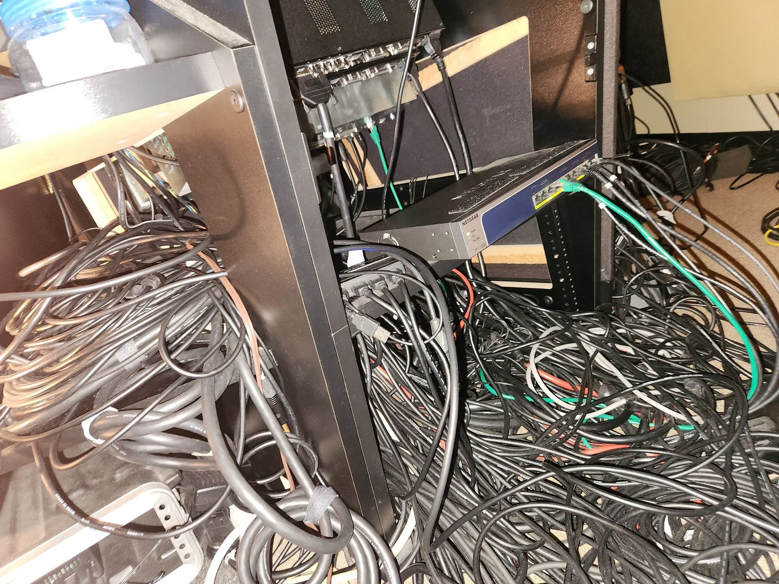
Every signal in your studio travels through cables. The quality of those cables directly affects sound quality, signal-to-noise ratio, frequency balance, and reliability. A cheap cable with poor shielding will pick up interference from every power line and fluorescent light in the building. A corroded connector will add crackle that sounds like the recording is damaged. A cable that is too long will lose high-frequency detail before the signal ever reaches the preamp.
Investing in quality cables preserves your signal over long distances, reduces degradation, and lasts years longer than budget alternatives. No matter how good your gear is, it will only sound as good as the cables connecting it. The cheapest cable in your signal chain becomes the ceiling for everything else—a $5,000 microphone running through a $4 mic cable is a $4 microphone with a famous nameplate.
Cable Types
suggest a correction“You have to learn how to plug something in and make it work. And that means that the signal levels, or maybe the impedances have to be in the ballpark.”
—George Massenburg (engineer; inventor of the parametric equalizer)
Studio cables fall into a small number of categories defined by what they carry (analog audio vs. digital data) and how they handle interference (balanced vs. unbalanced). The next several sections walk through each category and the connectors that go with it. Pay attention to the application notes—a cable that is perfect for one job (a TRS in a line-level patchbay) is the wrong cable for another (that same TRS run to a microphone, where a balanced XLR is the standard).
Analog Audio Cables
Analog audio cables carry an electrical audio signal from one piece of analog gear to another. The signal is called “analog” because the electricity flowing through the cable is analogous to the sound wave it represents. A 1 kHz sine-wave tone, for example, is a voltage varying from positive to negative and back 1,000 times per second. If that electrical signal drives a speaker cone, the cone moves in and out in that same pattern, producing a 1 kHz tone.
The main types of analog audio cables:
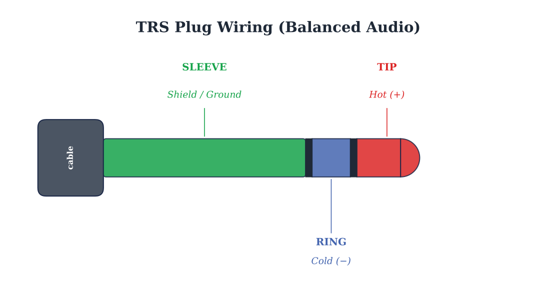
TRS (Tip Ring Sleeve) — 1/4-inch balanced cables with two black rings on the connector. Used for line-level devices and patchbays. If you see two rings, it is balanced.
TS (Tip Sleeve) — 1/4-inch unbalanced cables with one black ring. Used for electric guitars, bass, and keyboards. One ring = unbalanced. This is the cable you grab when a guitarist plugs in.
XLR — Three-pin balanced cables. The standard for microphones, and also used for line-level connections between professional gear. The locking mechanism prevents accidental disconnection—which is why XLR became the default for microphones, where a cable pulling loose mid-take is unacceptable.
RCA — Unbalanced cables used for turntables, phono devices, and consumer audio. You will see these in DJ setups, on older gear, and on the back of every Blu-ray player ever made. A studio doesn't run on these. They are the cable of the listener's living room, not the engineer's rack.
TT (Tiny Telephone) — Smaller gauge cables used in professional TT patchbays. Available in balanced (two rings) and unbalanced (one ring). When you open the back of a major commercial studio's console and see a wall of these, you know what serious infrastructure looks like.
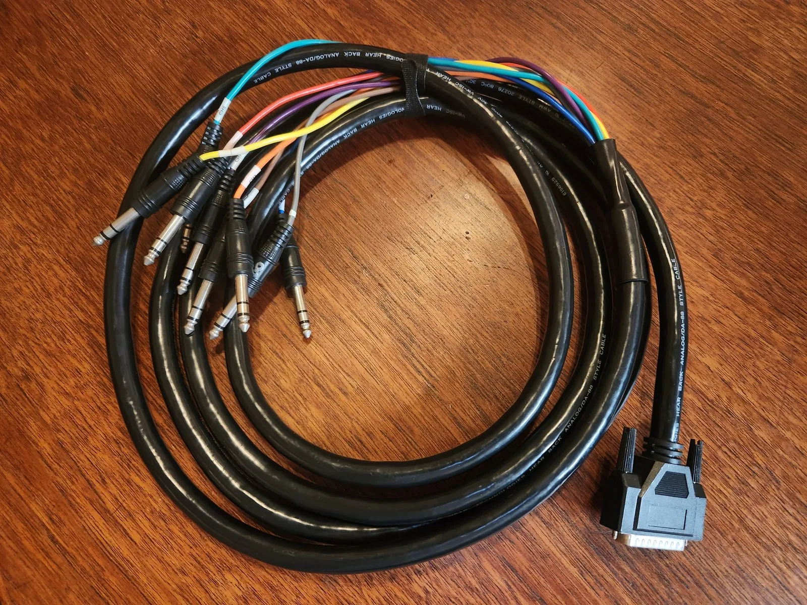
D-Sub (DB25) — Multi-channel connectors that carry 8 channels of audio through a single cable. Used in audio snakes connecting converters, patchbays, and multi-channel processors. One DB25 cable replaces eight individual TRS cables—the first time you swap a tangled snake nest for a single DB25 fan-out, the difference in load-in time is the only argument you will ever need.
Balanced vs. Unbalanced Cables
The first time I ran an unbalanced TS cable on a condenser microphone in a basement room I was sharing, I learned exactly what 60 Hz hum sounds like at concert volume—the cable picked up every fluorescent ballast and every adjacent power run in the building. Switching to a balanced XLR cable with the same mic in the same position dropped the noise floor by what felt like 30 dB and turned the recording from unusable into broadcast-ready. The microphone did not change. Neither did the room. The cable did. After that session I kept unbalanced runs short—15 to 20 feet at the very most—and any time a signal needed to travel farther, I converted it to balanced with a DI rather than trusting an unbalanced cable to make the distance.
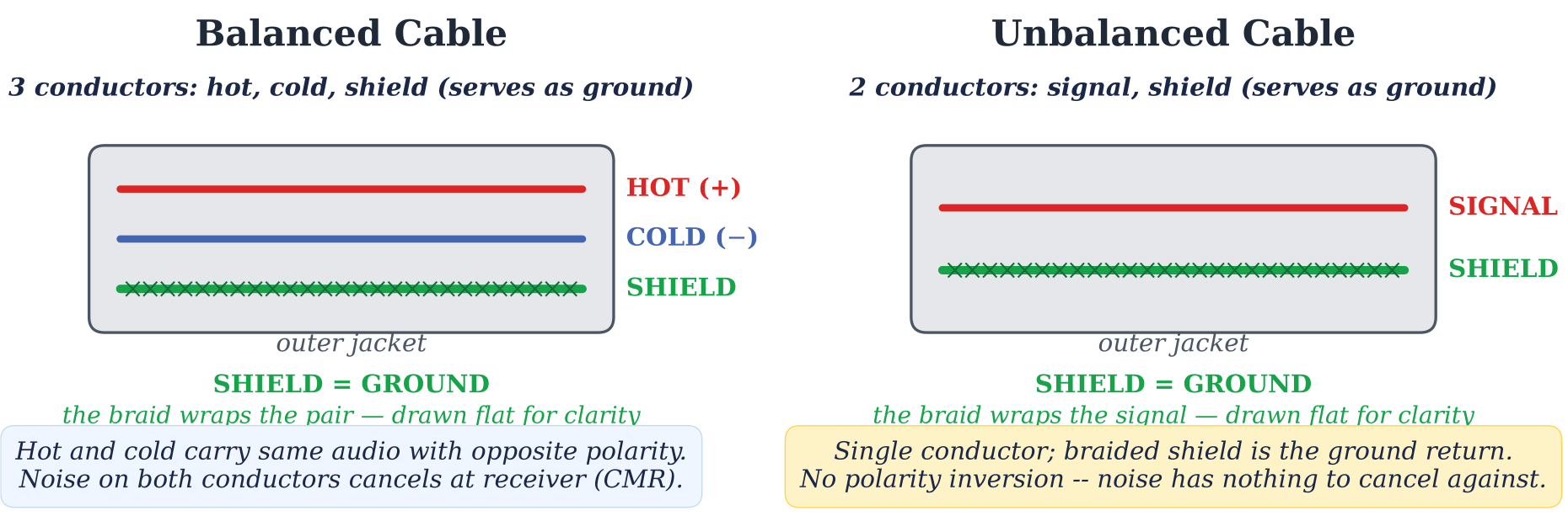
Balanced cables have three separate internal conductors: a positive (hot) audio lead, a negative (cold) audio lead, and a ground/shield. Unbalanced cables have only two: a single audio lead plus a ground/shield.
Balanced cables are far better at reducing noise through a principle called common mode rejection. Any electromagnetic interference picked up along the cable length appears equally on both the hot and cold conductors. At the receiving end, the cold signal is inverted and combined with the hot signal—the audio adds together while the noise cancels out. This allows balanced cables to run over hundreds of feet without significant degradation. Unbalanced cables are simpler and cheaper but are limited to about 25–30 feet before noise becomes problematic. (Ballou, ed., 2015)
Cable connectors typically come with silver or gold finishes. While silver is a marginally better conductor, it corrodes more easily. Gold-plated connectors (such as those made by Neutrik) maintain reliable contact over years of use.
There is an ongoing debate about whether studios should use balanced or unbalanced connections throughout. Some high-end mastering facilities connect all their gear with short unbalanced cables, arguing that balanced equipment requires extra circuitry or transformers that can color the sound. Others maintain that balanced connections are quieter and provide greater headroom. Unless an instrument specifically requires unbalanced cabling (guitar, bass, turntable), balanced connections are recommended for most studio wiring.
One wiring rule worth knowing by name: impedance bridging. A destination's input impedance should be at least ten times the source's output impedance—a mismatch costs signal level and can tilt the frequency response. (Ballou, ed., 2015) Modern line-level gear is designed around this rule, so it mostly takes care of itself; it becomes your problem with passive instruments and vintage equipment (the preamp chapter covers what variable input impedance does to a microphone's tone).
Cable length and high-frequency loss. Every analog cable acts as a small capacitor whose value scales with length. Typical instrument and microphone cable runs around 30–50 picofarads (pF) per foot, and that capacitance forms a low-pass filter with the source's output impedance. For a microphone (low source impedance) the effect is negligible at any reasonable length. For an unbuffered electric guitar pickup (high source impedance, around 10 kΩ or more), the same capacitance can audibly roll off treble above 25 feet. The fix is either a shorter cable, a buffered (active) DI at the instrument end, or a low-capacitance cable like Mogami W2524 or Canare GS-6. For balanced microphone or line-level runs, length is rarely the problem until you exceed about 100 feet.
Making Your Own Analog Audio Cables
The first cable I ever soldered worked. The second one didn't, and the third one shorted my ground to my cold and cooked a preamp input. That third cable taught me more about soldering than the first two combined—I had pre-tinned the conductors so quickly that a stray strand of shield braid had touched the cold-pin terminal under the heat-shrink, hidden from sight until the moment phantom power flowed. The lesson: every joint gets visually inspected before the housing goes on, every cable gets continuity-tested before it touches a mic input, and you never trust a cable just because it “looks fine.”
Soldering your own cables is a valuable skill that saves significant money over buying pre-made cables and means you will never be stuck waiting for a replacement when a cable fails mid-session. Always follow safety precautions when soldering: never touch the iron tip, wear long sleeves and eye protection, and work in a well-ventilated area.
To get started, you will need the following:
Connectors:
Neutrik gold TRS and XLR connectors (recommended).
Cable:
Canare or Mogami Star Quad balanced audio cable. Star Quad uses four internal conductors twisted into two pairs, providing superior noise rejection over standard two-conductor cable.
Soldering iron: — A temperature-controlled station such as the Weller WE1010NA.
Solder: — Kester 60/40 rosin-core solder.
Tools: — Wire cutters/strippers, small vise grip, pointed tools for de-braiding.
Cable tester: — Behringer CT100 or similar.
Step 1: Stripping the Cable
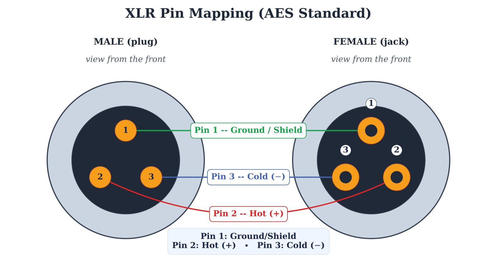
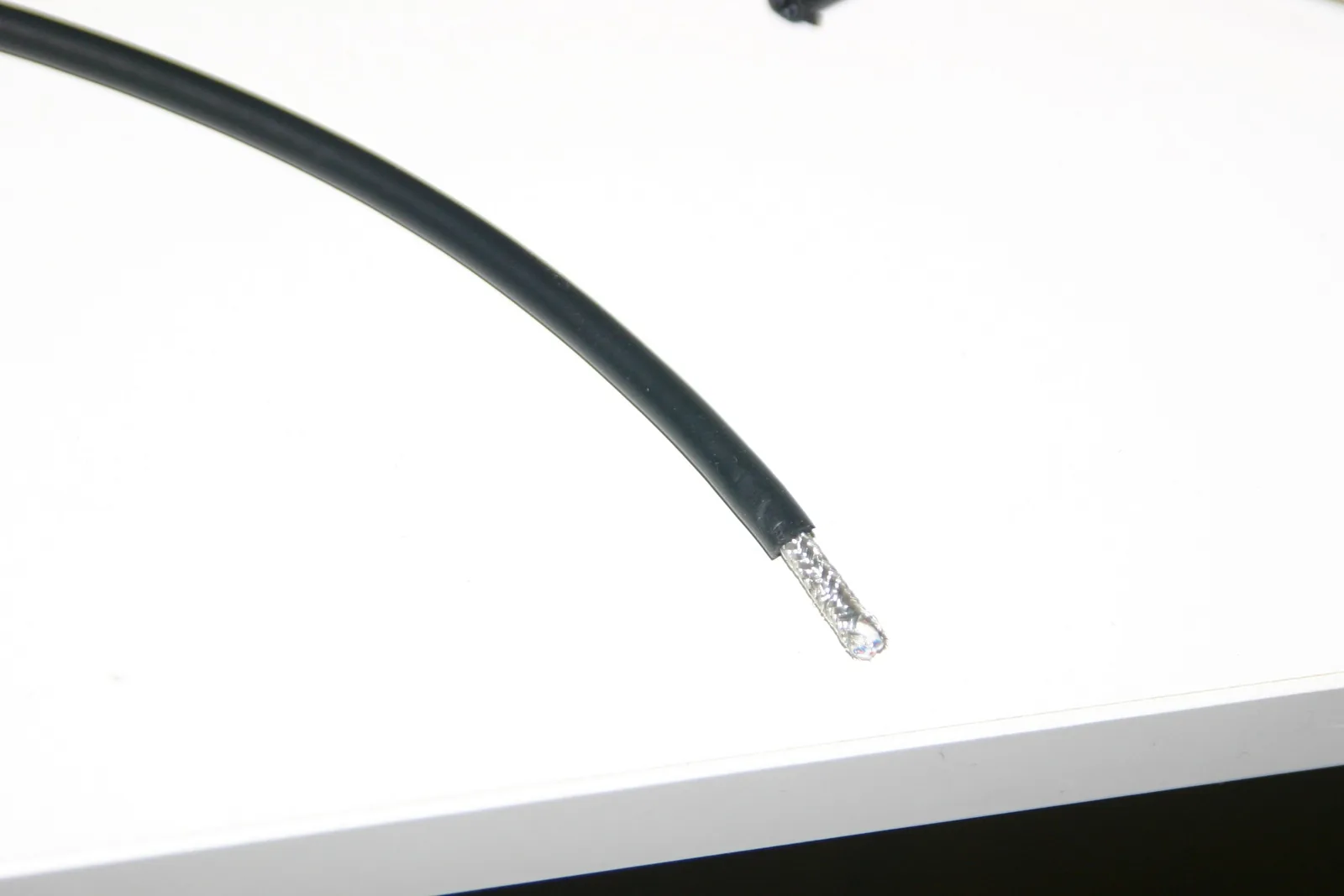
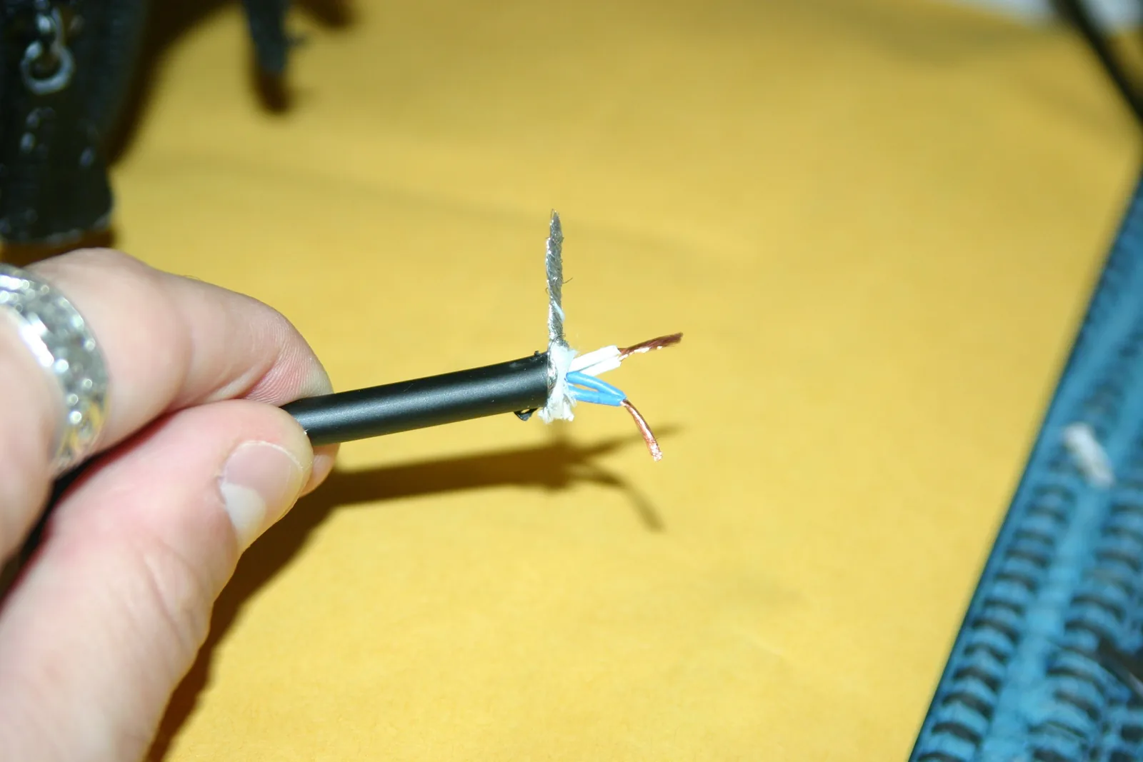
Cut the cable to the desired length. Strip about 3/4 inch of the outer jacket, being careful not to cut the internal wires. De-braid and twist up the ground/shield wire. Locate the two signal conductors and the braided shield—refer to the wiring diagram for pin assignment, since Star Quad insulation colors vary by manufacturer. On Star Quad cable, twist the two hot wires together and the two cold wires together. Strip about 1/2 inch of insulation from each conductor. Ensure the ground, hot, and cold wires are not touching each other. Finally, slide the connector barrel and any heat-shrink tubing onto the cable now—neither can be added after the joint is soldered.
Step 2: Tinning
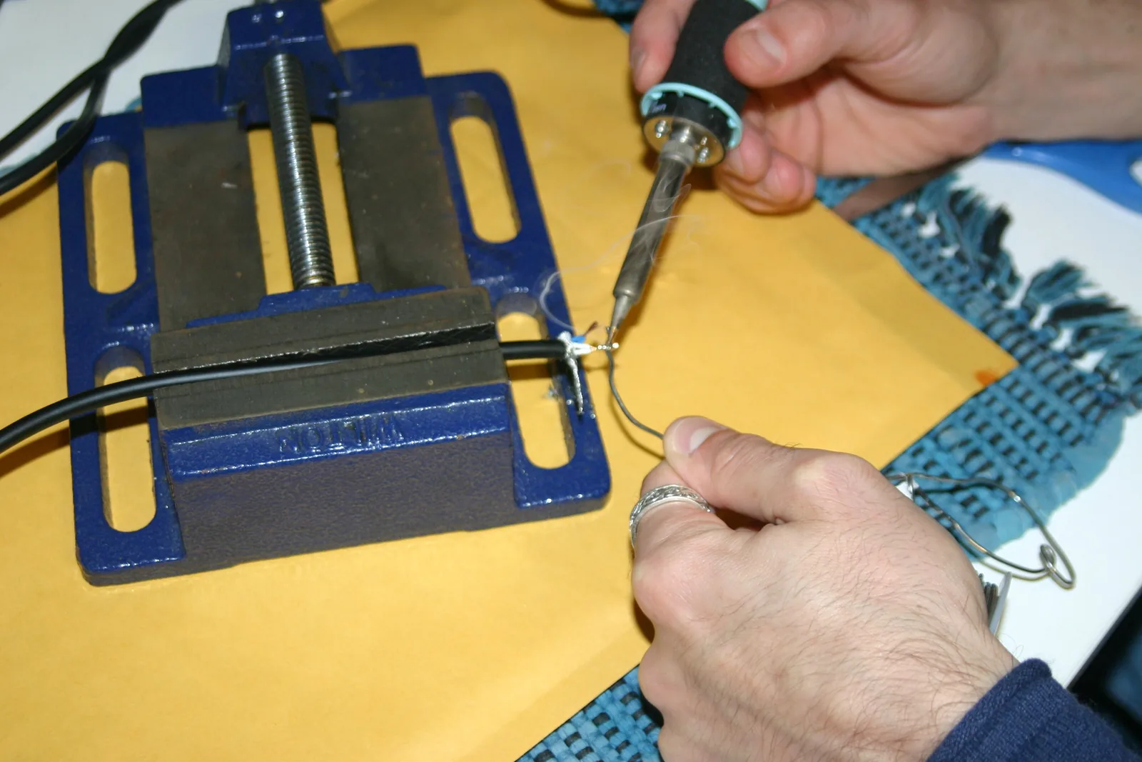
USE EXTREME CAUTION—the soldering iron is very hot. Clamp the cable in the vise grip. Heat the iron and ensure good ventilation. Carefully tin each conductor (hot, cold, and ground) by melting a thin coat of solder onto the exposed metal. Tinning makes the final soldering step much easier and creates a stronger joint.
Step 3: Soldering
Before soldering, slide the connector's barrel/housing onto the cable first—if you forget this step, you will need to desolder and start over. Clamp the connector in the vise grip. Pre-tin the connector's solder points. Place each conductor on its corresponding terminal (per the wiring diagram) and melt them together. Ensure all connections are secure and that no wires are touching each other. Assemble the strain relief and connector housing, then test with the cable tester.
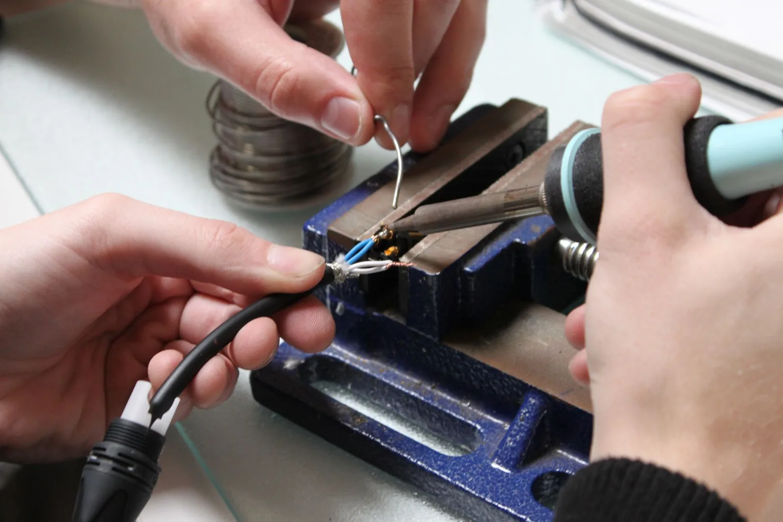
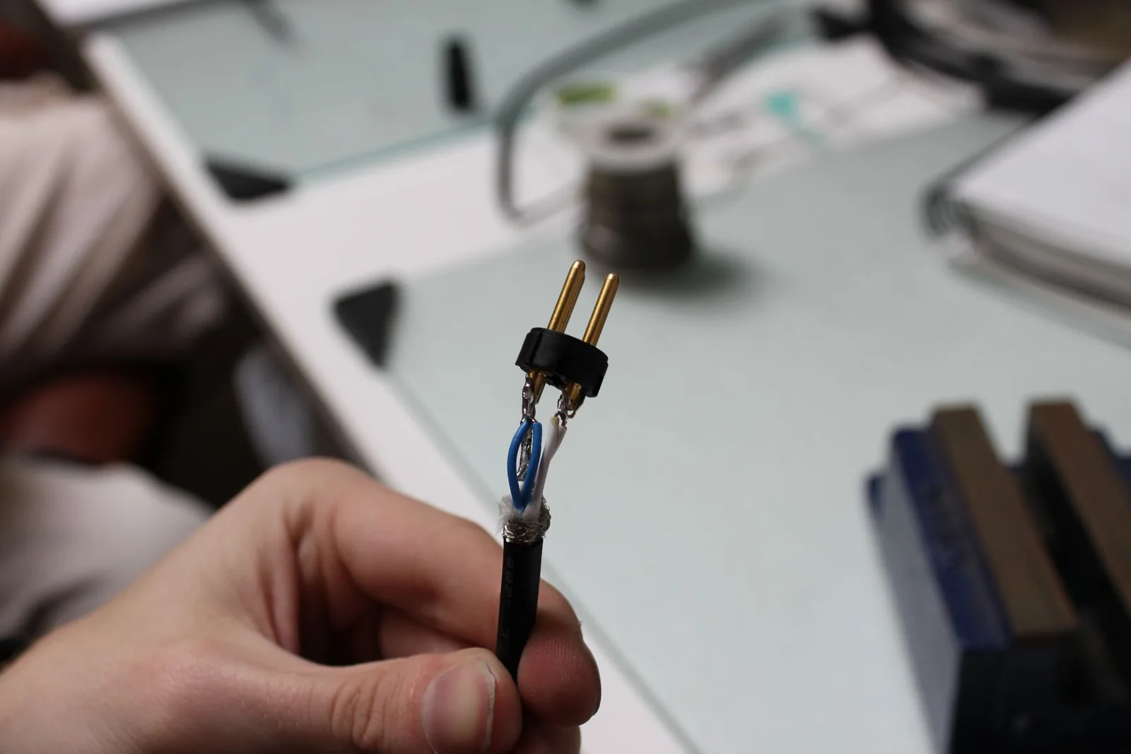
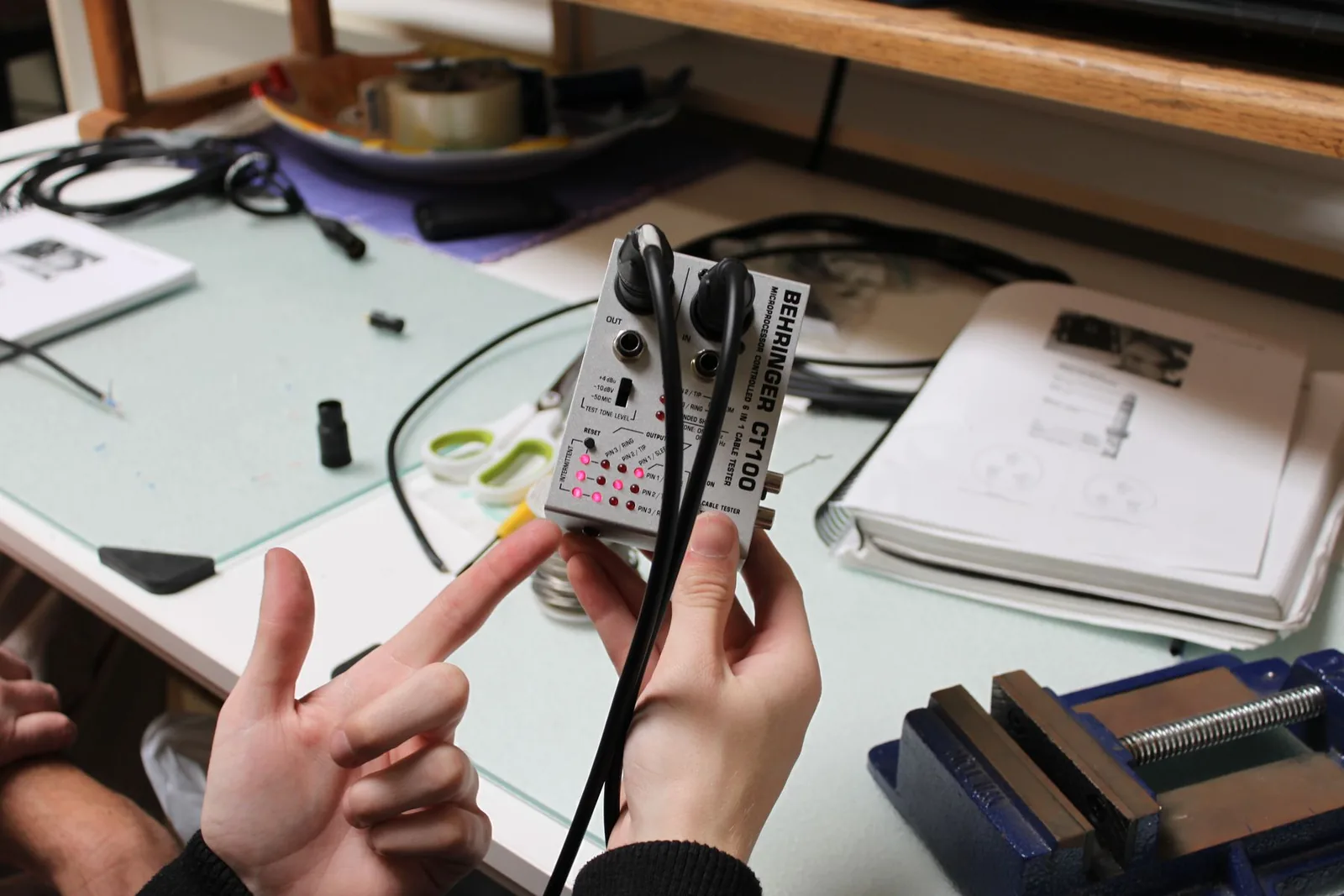
If soldering is not practical, Mogami Gold cables are the industry standard for pre-made cables—they provide excellent audio quality and outstanding durability. Companies like Redco and ProAudioLA also build custom cables to specification using high-quality components.
A note on speaker cable. Cable that carries amplifier output to a passive speaker or subwoofer is a different beast: it carries far more current than line-level audio and uses thicker conductors. Wire gauge is what matters here—14 AWG is the minimum for short studio runs (under 25 ft), 12 AWG for longer runs or higher-power monitors. Active studio monitors (which have built-in amplifiers) do not use speaker cable at all—they accept balanced line-level signal over TRS or XLR. Speaker cable in the studio is mostly an issue when wiring soffit-mounted main monitors or subwoofers powered by an external amplifier. The same rule applies to the cable between a guitar amp head and its speaker cabinet: that is a speaker cable, not an instrument cable. They look identical (both 1/4-inch TS), but an instrument cable in that spot can overheat and damage the amp's output transformer—always use a proper unshielded speaker cable between a head and a cab.
Digital Audio Cables
When I built my first real studio, I was tracking on a Digidesign 003—a great little interface, but only eight inputs. The day I needed more, I did not buy a bigger console or an expensive analog snake; I added a high-quality eight-channel converter (a Lynx Aurora) and connected it to the 003 over a single optical ADAT cable on the back, clocking the 003 to the Aurora's better clock. I doubled my input count and improved the sound of everything I recorded, all over one lightpipe. Digital cables are not just a convenience or a way to save money—they are how a small studio scales and how it improves, and for formats like ADAT they are simply a necessity. I could not run my room without them.
Digital audio cables carry sound as binary code—strings of 1s and 0s—rather than as a continuously varying voltage. They can transfer multiple channels through a single connection with excellent clarity, all locked to a sample-rate clock that keeps every device on the chain in lockstep. One distinction up front: a digital audio cable carries audio between two digital audio devices (an interface to a converter, a converter to a console)—that is what this section covers. The cables that connect an audio device to a computer (USB, Thunderbolt, DigiLink) are a separate category, covered later under Computer and Interface Connections. The protocols you will encounter most:
AES/EBU (AES3) is the professional standard: two channels over balanced XLR, up to 24-bit/192 kHz, with cable runs up to 100 meters at standard rates (shorter at 192 kHz). The 110-ohm balanced connection resists interference, making it the choice for critical studio and broadcast connections—the format broadcasters have trusted for decades because it simply works.
S/PDIF is the consumer counterpart: two channels over coaxial RCA (75-ohm) or optical TOSLINK. Shorter runs—10 meters coaxial, 5 meters optical. Same data format as AES/EBU but unbalanced and more susceptible to interference. TOSLINK fiber should never be bent sharply—it can permanently damage the optical core. You will see S/PDIF on home gear (the back of every CD player, AV receiver, and laptop with a digital-out); you will rarely see it on the back of a tracking-room rack.
ADAT Lightpipe transmits eight channels at 24-bit/48 kHz over one TOSLINK cable. At 96 kHz, channel count drops to four via S/MUX; at 192 kHz it drops to two. ADAT is the most common and affordable way to expand your interface's input count—one cable replaces eight analog connections, and you can buy an 8-channel ADAT-output mic preamp for less than what an analog snake plus converter costs.
MADI transmits up to 64 channels at 48 kHz (32 at 96 kHz) over a single coaxial BNC or fiber cable, with runs up to 2,000 meters on fiber. Used in large studios, broadcast, and live sound where high channel counts and long cable runs are essential. MADI is what you reach for when the recording truck is in the parking lot and the band is on the stage—one fiber pull replaces what used to take a crew with a Yale cart and an hour of cable wrangling.
Audio over IP: Dante and AES67
Imagine replacing an entire analog snake with a single Ethernet cable. That is what Audio over IP has made possible—and it is why the heavy copper snakes that used to require a crew to load in and out of a venue have largely disappeared from professional installations.
Dante, developed by Audinate, transmits hundreds of channels of uncompressed audio over standard Ethernet with latency as low as 150 microseconds. It uses off-the-shelf Cat5e/Cat6 cables and network switches, making installation dramatically simpler and cheaper than traditional multichannel wiring. Dante is now built into more than 4,000 products from over 600 manufacturers including Focusrite, Yamaha, Shure, and JBL.
AES67 is the open interoperability standard allowing different AoIP systems to communicate. Dante devices can be configured for AES67 compatibility, enabling cross-platform interoperability with systems like Ravenna and Livewire.
Setting up a Dante system. Most professional Dante installations follow the same workflow. Connect every Dante-enabled device (interfaces, headphone amps, console, the Dante Virtual Soundcard running on the computer) to a single managed gigabit network switch via Cat5e or Cat6. Install Dante Controller—free from Audinate—on a computer connected to the same network. The Controller gives you a routing matrix: rows are sources (channel outputs), columns are destinations (channel inputs). Click a cell to route a channel from any device to any other device on the network. That is it. There is no XLR to label, no analog snake to roll up, no patch cable to terminate. Save the routing as a preset and you can recall an entire studio's signal flow with a click. Latency is so low (as low as 150 microseconds at 48 kHz, the same delay sound takes to travel about five centimeters of air) that engineers cannot reliably distinguish a Dante connection from a direct analog cable.
Computer and Interface Connections
Audio interfaces connect to computers through a small number of data-cable formats. The two you will encounter every day are USB and Thunderbolt; the other two—DigiLink and BNC—are for specific professional setups.
USB is the most common audio-interface connection: USB 2.0 (480 Mbps) handles most home and project work, USB 3.x scales up to 20 Gbps, and USB-C connectors have become the modern default on both computers and interfaces (USB-C is the connector; the speed underneath it can be USB 2.0 or USB 3.x, so check the spec, not just the plug). USB is fine for tracking a few inputs at a time and for any mix-only work.
Thunderbolt is what serious tracking sessions run on. Thunderbolt 3/4 (40 Gbps) share the USB-C form factor; Thunderbolt 5 reaches 80 Gbps. The combination of high bandwidth and low latency makes the difference real and audible—the first time I tracked drums and a full band over Thunderbolt at sub-2 ms round-trip latency, the players stopped flinching at the headphone feed and started playing. USB chokes when you push it; Thunderbolt holds up. For any session with high channel counts, real-time monitoring through plugins, or 96 kHz sample rates, Thunderbolt is not optional.
DigiLink is Avid's proprietary connection for Pro Tools HDX and HD Native systems, used to connect Pro Tools hardware to Avid or compatible converters. A single DigiLink Mini connection carries up to 32 channels of I/O; each HDX card has two ports, for 64 channels of input and output per card. If you walk into a major commercial Pro Tools room, DigiLink is what is going on behind the console.
BNC is the odd one out among these computer connections: as used here it carries no audio and no computer data (the same BNC connector also carries MADI audio, as we saw—in this context the job is clock only). It is a clock/sync connection—a master clock sends a timing reference over 75-ohm BNC cable to keep every digital device on the chain locked in sample-accurate sync, preventing the clicks, pops, and artifacts that come from clock drift. (You only need it when chaining multiple converters; a single interface clocks itself.)
Headphone Distribution Amplifiers
A tracking session with more than one performer needs more than one headphone mix—and most audio interfaces only provide one or two headphone outputs. A headphone distribution amplifier (or “cue system”) solves this by taking a master mix from the engineer and providing multiple independent headphone outputs, each with its own volume control. The simplest units (Behringer HA8000, ART HeadAMP6) provide six to eight identical headphone feeds. More advanced systems (Furman HRM-16, Hear Technologies, Aviom A360) give each performer their own personal mixer to balance their own headphone mix in real time—the singer can turn up their own vocal, the drummer can turn down the click, and nobody bothers the engineer between takes. For any session involving a band tracking together, a distribution amp is the difference between an efficient session and a frustrated one.
MIDI Cables
MIDI (Musical Instrument Digital Interface) cables transmit performance data—not audio—between controllers, synthesizers, drum machines, and computers. Traditional MIDI uses 5-pin DIN connectors, but USB-MIDI has largely replaced 5-pin DIN in modern studios. Most current MIDI controllers connect directly to the computer via USB, eliminating the need for a separate MIDI interface. We explore MIDI in detail in Chapter 10.
Patchbays
suggest a correction“The first thing I had to learn about audio engineering was signal flow. You have to know how to get the audio signal from the microphone to the recorder and back to the speakers so you can hear what you are doing.”
—Roger Nichols (engineer, Steely Dan; seven-time Grammy winner)
If cables are the nervous system, the patchbay is the central switchboard—the single place where every signal in the studio can be re-routed, split, or interrupted in seconds. Master it and you can re-wire an entire signal chain mid-session without touching the back of a single rack. Ignore it and you will spend the rest of your career on your knees with a flashlight.
The first time I saw a fully wired patchbay, I thought it was incomprehensible—a wall of identical jacks with patch cables crisscrossing everywhere. It looked like a telephone switchboard from the 1940s. But once I understood the logic behind it, I realized it was the single most time-saving device in the studio.
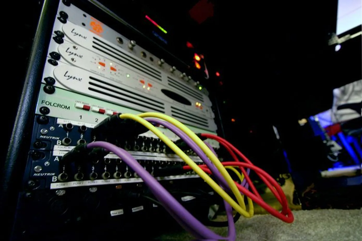
Patchbays are routing panels that bring all the inputs and outputs of studio gear to a single, convenient location. Without a patchbay, changing the signal path would require reaching behind racks to re-route cables every time—time-consuming and error-prone. A patchbay lets the engineer route, split, and re-route signals using short patch cables on the front panel.
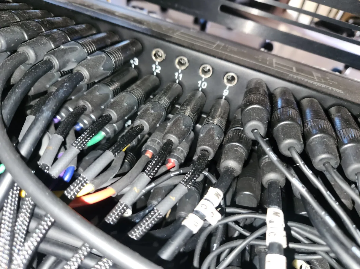
The back of the patchbay is where all studio gear connects permanently. The signal flows internally to corresponding jacks on the front. From the front, the engineer uses patch cables to route signals between devices. The top row is typically reserved for device outputs and the bottom row for device inputs.
Each column of a patchbay is a separate card with four jacks (two front, two back). Each column is independent from the others unless connected by a patch cable. The four jacks within each column may be internally interconnected depending on the patchbay's configuration.
Color-coding your patch cables makes complex routing visible at a glance—use one color for converter sends, another for returns, another for effects. Label every patchbay point clearly (a label maker is one of the best investments in any studio). When a session calls for a specific signal chain, you should be able to patch it in seconds without thinking. The engineers who are fastest on the patchbay are the ones who wired it themselves and know every connection by heart.
Patchbays come in two main connector formats: TRS (1/4-inch jacks, the same connector as standard line-level cables) and TT or Bantam (a smaller-format 0.173-inch connector). TRS patchbays are inexpensive (often under $200 for a 48-point unit), use cables you may already own, and dominate home and project studios. TT patchbays cost considerably more and require dedicated TT patch cables, but they pack twice the density into the same rack space, use a more reliable contact mechanism, and have been the standard in commercial broadcast and recording facilities for decades. If you can afford TT and have rack space at a premium, choose TT—you will pay for it once and never re-wire it. For most home studios, TRS is the right answer.
I went TRS in my own studio for a practical reason as much as a financial one: every other cable and connector in the room—guitar cables, line-level patches, headphone extensions—was already 1/4-inch TRS or TS, which meant my soldering bench only had to stock one family of plugs and one set of jacks. Adding TT would have meant another box of connectors, another set of crimp tools, and another spare-cable inventory to maintain. If you ever build cables yourself, the format you already use is the format that will keep you fastest at 1 AM when something snaps mid-session.
Scale and layout follow the format. A typical home or project room runs one or two 48-point TRS bays in a single rack space—enough to surface the converter ins and outs, two or three outboard processors, and the headphone amp inputs. A commercial facility commonly runs four or more TT bays at 96 points each, organized by signal type from top to bottom: converter sends and returns, mic-pre outputs, dynamics inserts, EQ inserts, effects sends and returns, and finally the console buses. The layout is the same idea at different scale—outputs always on the top row, inputs always on the bottom row, related gear grouped on adjacent columns—but the commercial bay carries the entire facility's signal traffic on its front panel, where any signal can reach any destination in one patch.
Patchbay Configurations
The first time someone explained half-normalled to me, my reaction was, “why is this a thing?” Then I tried to set up a parallel-compression bus on a normalled patchbay, broke the dry signal three times, and finally understood: half-normalled lets you tap a signal without losing the original path. From that moment, patchbay configurations stopped being abstract and became the most useful single concept in my studio's signal flow.
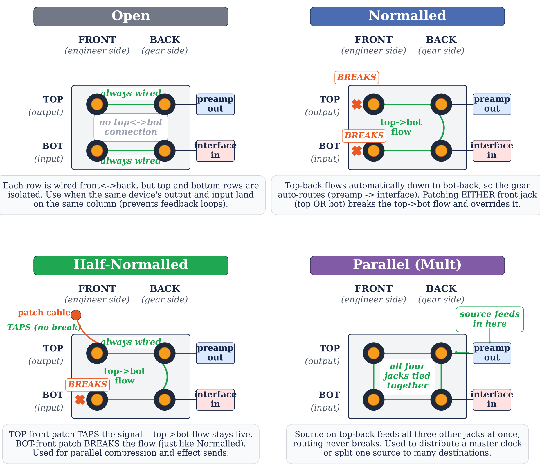
There are four main configurations that determine how signal flows between the top and bottom jacks within each column:
Open configurations have no automatic flow from top to bottom—signal passes straight through from back to front on each row independently, and a patch cable must be used to connect a top-row output to a bottom-row input. Use open whenever the output and the input on the same column belong to the same device (to prevent feedback loops)—for example, if the same compressor's input and output land on the same patchbay column.
Normalled is the most common configuration. Signal flows automatically from the top jack to the bottom jack without a patch cable—and any patch cable plugged into either front jack breaks that flow. Use normalled when the output and input on a column belong to different devices that should be connected by default (preamp output on top, converter input on bottom is the classic case).
Half-normalled is the most useful single configuration in a professional studio, and the one that probably justifies the patchbay's existence on its own. It behaves like a normalled connection until you patch into it: plugging a cable into the top front jack does not break the automatic flow—it splits the signal, sending it both to its original destination and to wherever the patch cable goes. Plugging into the bottom front jack does still break the chain. Use half-normalled for parallel-compression buses, effect sends, or any time you want to tap a signal without interrupting its normal path.
Parallel sends the signal from the top back jack to all three other jacks simultaneously, and the routing is never broken regardless of what is patched. Use parallel when a single signal needs to feed several destinations at once—for example, splitting one source three ways to feed multiple headphone amps, or sending a single output to several processors in parallel.
Patchbay Example: Hardware Inserts
A common use of patchbays is routing hardware “inserts” in the DAW. An insert sends signal out of the DAW through a D/A converter channel, through an analog processor, and back into the DAW through the same A/D converter channel. With a half-normalled or normalled patchbay, this can happen automatically—the converter output (top row) flows directly to the processor input (bottom row) without any patch cables.
Things get creative when chaining multiple processors on a single insert. For example, to route signal through a preamp, then a compressor, then an EQ—all on the same converter channel—the engineer patches the preamp output to the compressor input, the compressor output to the EQ input, and the EQ output to the converter return. The patchbay makes this routing quick and reversible.
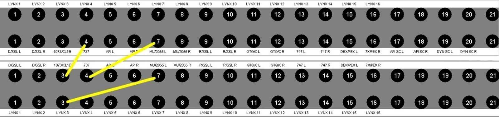
Remember: outputs (top row) always connect to inputs (bottom row)—unless the connection is already established automatically through a normalled, half-normalled, or parallel configuration.
Power and Noise
suggest a correctionCables carry signal, but they also pick up noise—from the AC line that powers your gear, from radio transmitters and Wi-Fi routers, from any circuit that shares a ground path with audio. The next two sections cover the two main noise problems in any studio (ground loops and RF/EMI interference) and the troubleshooting tools that solve them.
Power, Grounding, and Noise
One of the most common problems in any studio is the ground loop—a low-frequency hum (60 Hz in North America, 50 Hz in most other countries) caused when two or more pieces of gear are connected to different electrical grounds, creating a loop through which current flows. I once spent an entire afternoon chasing a 60 Hz hum through a studio, disconnecting and reconnecting gear one piece at a time. The culprit? A video monitor on a different circuit than the rest of the rack. Moving it onto the rack's circuit fixed it in seconds—after four hours of detective work.
If you hear a steady hum that changes when you connect or disconnect devices, you likely have a ground loop. The classic diagnostic: disconnect everything and add devices back one at a time until the hum appears. The last device you connected is part of the loop. From there, work through the fixes in order of cost and complexity.
Try star grounding first. Connect all devices to the same outlet strip on the same circuit. A common ground reference eliminates the voltage difference that causes the loop, and it costs nothing but a power strip you probably already own. Most studio hum problems disappear at this step alone.
If that does not work, add a power conditioner. A quality unit (Furman or SurgeX) provides filtered, regulated AC, protects gear from surges, and filters high-frequency noise off the line. In a professional studio every piece of gear should run through a conditioner—it is the cheapest insurance you can buy.
A note on the AC cables themselves: most rack gear connects with an IEC C13/C14 cable (the rectangular three-pin “kettle lead” you see on the back of nearly every studio component). Higher-current devices—power amps, large consoles, mastering compressors—may use the heavier C19/C20 variant, identifiable by its squarer hood and thicker conductors. Do not mix and match: a C13 plug fits only a C14 inlet, and forcing a smaller cable into a high-current load is a fire risk. Keep a small supply of spare IEC cables in the studio in known-good condition; they fail more often than people think, and they fail silently—intermittent dropouts and unexplained pops are sometimes nothing more than a tired AC cable.
If hum persists in the audio path itself, reach for a ground lift on a DI box. Bass guitars and keyboards are the most common offenders. A DI with a ground-lift switch breaks the loop between the instrument and the rest of the signal chain in seconds. Before you start chasing exotic solutions, try this one.
For stubborn problems, use an audio isolation transformer. A device like the Ebtech Hum Eliminator breaks the ground reference within the audio signal path without affecting the audio itself. This is what you reach for when a long cable run between two grounded devices in different rooms is causing the loop and star grounding is not practical.
Beyond conditioning: balanced and three-phase power. The same balanced-line trick that saves long cable runs exists for the AC line itself. A balanced power unit uses an isolation transformer to split 120 V into two legs of 60 V each, opposite in polarity around ground—so the noise each leg couples into your audio wiring arrives equal and opposite, and cancels, exactly like the noise on a balanced cable. In a room full of interconnected gear it can drop the noise floor audibly and quiet stubborn hums that survive every ground-lift in the rack. It is facility-grade medicine (a properly sized unit is heavy and not cheap), installed at the rack or room level, not a power strip. Larger commercial facilities go a step further and bring in three-phase power, splitting lighting, HVAC, and audio across separate phases so the noisiest loads in the building never share a leg with the studio. You do not need either to make records—but when you walk into a major facility and the noise floor feels like a vacuum, this is part of why.
RF and EMI Interference
Radio-frequency interference (from cell phones, Wi-Fi routers, and broadcast transmitters) and electromagnetic interference (from power transformers, fluorescent lights, and computer monitors) can also introduce noise. Keep audio cables away from power cables—cross them at 90-degree angles when they must intersect. Use shielded cables. Keep cell phones out of the recording area. If you hear a rhythmic buzzing that sounds like digital Morse code, a cell phone is almost certainly the culprit.
I once ran a studio that sat within a few hundred yards of a commercial radio tower, and RFI was a constant battle—ungrounded guitar cables would pick up the local AM station as a faint, ghostly broadcast bleeding through the recording. The fixes were aggressive: every cable run shielded, every connector properly grounded, ferrite chokes on the worst offenders, and (the largest single improvement) replacing every single-coil pickup with a humbucker for any guitar tracking session in that room. Wi-Fi routers and Bluetooth transmitters are a milder version of the same problem—keep them at least six feet from the tracking position and outside the line of any unshielded cable run.
The Invisible Foundation
suggest a correctionA studio with world-class microphones, pristine converters, and a hundred-thousand-dollar console is only as good as the weakest cable in its signal chain. A single corroded solder joint or a poorly shielded run past a power conduit can introduce noise that no amount of processing will remove.
Learn to solder—not as a hobby, but as a professional skill. An engineer who can build a custom cable on the spot, repair a broken connector between takes, or wire a patchbay from scratch is an engineer who never has to wait for someone else to fix the problem. It is fast to learn, inexpensive to practice, and it will pay for itself the first time a cable fails during a session.
Cable management is also a signal of professionalism that clients notice even if they cannot articulate why. A studio with neatly dressed cables, clearly labeled patchbays, and organized racks communicates competence before a single fader is touched. Take pride in the infrastructure. Trace every signal from source to destination. Know which connections are normalled and which require manual patching.
Here is the part nobody tells you: nobody compliments a clean rack. No client points at a neatly dressed patchbay and says “wow, the wiring is gorgeous.” No producer leans over the console mid-session and remarks that the ground is silent. That is precisely the point. Infrastructure that draws no attention is infrastructure that works. The cables are not what people will remember about your studio—the records that come out of it are. But the cables are what makes those records possible. Build the foundation so quietly competent that no one ever has to think about it, and you will spend the next twenty years recording music instead of chasing problems no one can see.
Build the habit early: dress every cable as if a client will inspect it tomorrow, label every patch as if you will not touch it for a month, and coil and route every line as if someone else will have to find and trace it without you in the room. These rituals look fussy until the day they save a session, and they always save a session. The studios I respect most are the ones where every cable has a story—and a label.
Review Questions
Work these before moving on — every question is answerable from this chapter. Written answers live in the instructor Answer Key, available to course adopters.
- What are the two main categories of audio cables?
- List three types of analog audio cables and when each is used.
- True or False: Balanced cables have three conductors; unbalanced have two.
- Explain common mode rejection in balanced cables.
- List four types of digital audio connections.
- What is Dante, and why is it important in professional audio?
- What is a patchbay, and why is it used?
- Patchbay top row = ________; bottom row = ________.
- Describe the four patchbay configurations.
- When would you use half-normalled instead of normalled?
- Route a signal through three processors on a single insert using a patchbay.
- What is a ground loop, and how do you fix it?
- List the tools needed to solder an XLR cable.
- Describe the three soldering steps (stripping, tinning, soldering).
- How many channels does ADAT carry at 48 kHz? At 96 kHz?
- Name two causes of RF/EMI interference and how to prevent them.
- What is star grounding?
- Max cable length for unbalanced cables? Why can balanced run longer?
- What is DigiLink?
- Gold vs. silver connectors—what is the advantage of gold?
- Watch IN THE STUDIO with Asaf Fulks: Episode 9 [Soldering Audio Cables] and be prepared to solder your own cable.
- Watch IN THE STUDIO with Asaf Fulks: Episode 6 [How to Wrap a Cable] and be prepared to wrap a cable properly.
- A producer's project studio currently uses short unbalanced TS cables to connect all outboard gear within a single room. The studio plans to expand into an adjacent room 75 feet away, adding a second set of converters, outboard processors, and a headphone distribution system. Evaluate whether the studio should (a) continue with unbalanced cabling, (b) switch to balanced XLR/TRS throughout, or (c) implement a Dante/AoIP network for the inter-room signal routing. What technical factors and practical trade-offs should drive the decision for each leg of the signal chain?
Studio Exercise: Build Your Own Cable
Soldering a working cable is the moment cables stop being magic and start being something you control. This exercise builds a real, professional skill the chapter teaches.
Setup. You will need:
- One length of balanced audio cable (Canare or Mogami Star Quad, 6–10 feet).
- Two connectors: either two Neutrik gold XLRs (one male, one female) for a microphone cable, or two TRS plugs for a line cable.
- A temperature-controlled soldering iron (Weller WE1010NA or similar), Kester 60/40 rosin-core solder, wire cutters/strippers, a small vise, and heat-shrink tubing.
- A cable tester (Behringer CT100 or any continuity tester).
Method. Follow the three-step process the chapter describes: strip the outer jacket and the inner conductors, tin each conductor with a thin coat of solder, then solder each conductor to its correct terminal on the connector (slide the housing onto the cable before you solder, or you will start over). Reference the XLR or TRS wiring diagram earlier in the chapter for pin assignments. Test the finished cable on the cable tester—all three pins (or tip/ring/sleeve) must read continuity, and no two conductors should short to each other or to ground.
Submit. A photograph of the finished cable, a photograph of the cable tester showing all pins read correctly, and a 100-word reflection naming the part of the process that was hardest—and what you would do differently next time.
Bonus (any of the three). (1) Solder a second cable in under 15–20 minutes. (2) If soldering equipment is unavailable, document a complete signal-flow diagram of your existing studio with every cable type labeled (XLR / TRS / TS / digital / power)—turn it in as a labeled photograph or hand-drawn diagram. (3) Route a signal through three outboard processors on a single insert using a half-normalled patchbay, document the patch cables you used, and submit a photograph of the patchbay before and after.